This page contains information to build a scalable 25V DC to 220V AC sinewave inverter. The basic inverter module has a 400W capability. These basic inverter modules can simply be connected in parallel to make bigger inverters.
The example described here has 5 modules connected together to provide a 2000W capability.
The Inverter block diagram is shown in the figure below.
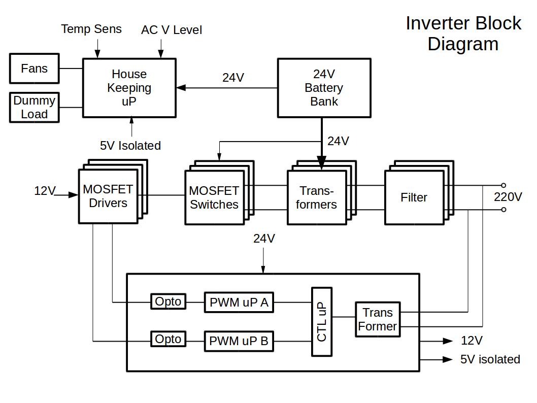
All components are available from RS Components. (http://za.rs-online.com/web/). The transformer is type RKD 400/2×18 (http://za.rs-online.com/web/p/toroidal-transformers/7529393/)
The MOSFET Switches, Transformer and Filter circuit of a basic module is shown in the Inverter Power Stage figure below.
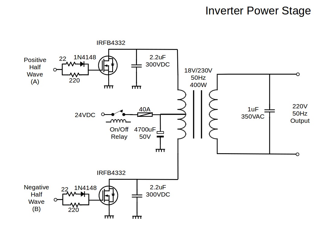
When connected in parallel with other modules, the 220V 50Hz Output is connected together in phase, and similarly for the positive and negative half wave inputs, A and B. The 24V DC supply from the solar batteries is also connected in parallel via bus-bars to the different modules.
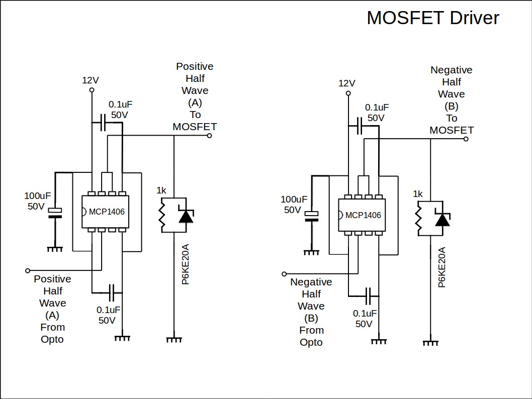
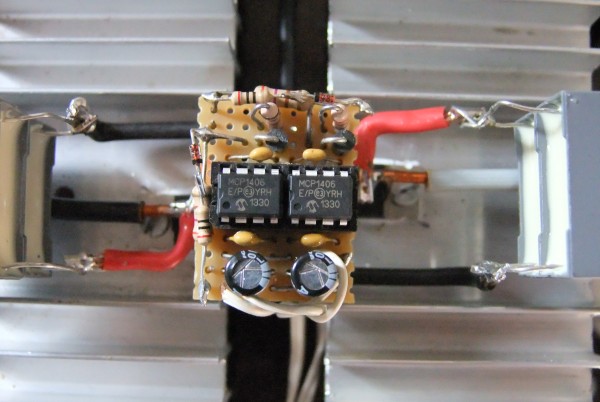
The source for inputs A and B, across all modules working in parallel, must be the same signal generator. These signals are provided by the Processors stage. These Processor stage signals are connected to the MOSFET Drivers which are connected to the Inverter Power Stage inputs as shown below.
The positive and negative halves of the sinewave is generated by two separate micro controllers A and B as indicated in the Sinusoidal Pulse Width Modulation (SPWM) circuit below. This circuit provides the SPWM signals for all Mosfet Driver modules connected in parallel. (fan-out style).
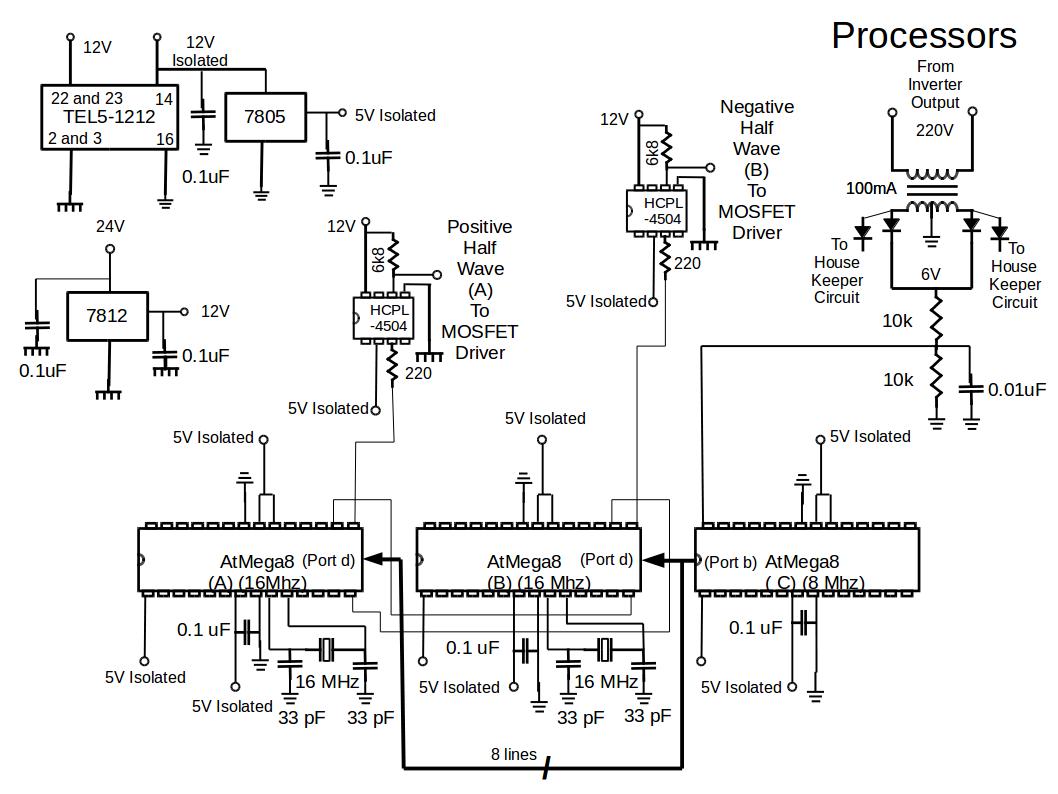
The two SPWM processors are controlled by a third processor (C) which monitors the AC sine wave energy content (Root Mean Square (RMS) value). It commands the SPWM processors to increase or decrease the SPWM output. Processor C ensures that the Inverter output voltage remains at 220V RMS AC at different Inverter loads.
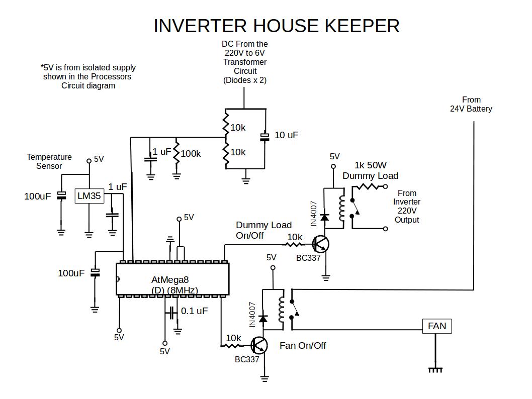
The fourth processor monitors the temperature of the MOSFETs and the peak voltage level of the Inverter AC output. This processor ensures that the temperature of the MOSFETs stays below 65 degrees Celsius, by switching on/off the Inverter fans. (2 fans, one in front and one at the back of the inverter, of type RS Components Nr 126-565.) The AC peak voltage level is monitored to prevent the inverter from a no-load situation which could cause oscillation. A dummy load (1 k ohm, 50W) is connected to the output of the Inverter in the event of no-load conditions. This housekeeping micro controller circuit is shown in the next picture.
The software programs were created and compiled with BASCOM AVR and the programmer used is the USB-ISP programmer, both available from www.mcselec.com
The program listings are given here:
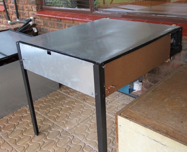
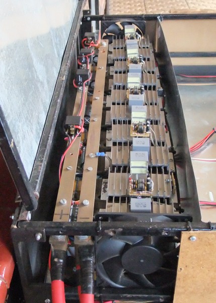
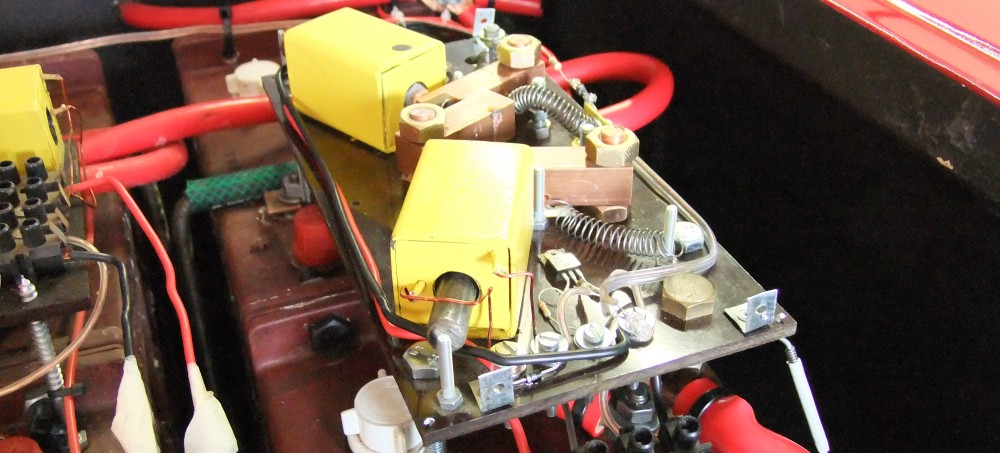
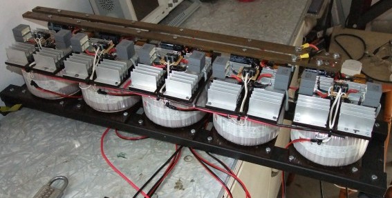
Some more detail about the construction and layout of the Inverter can be seen in the following pictures.
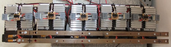
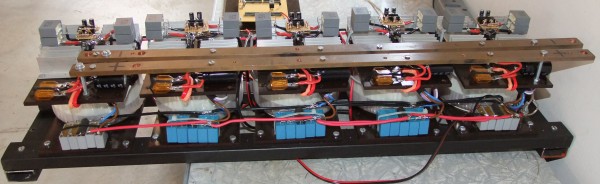
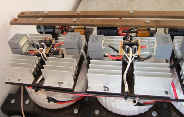
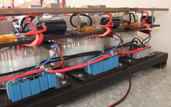
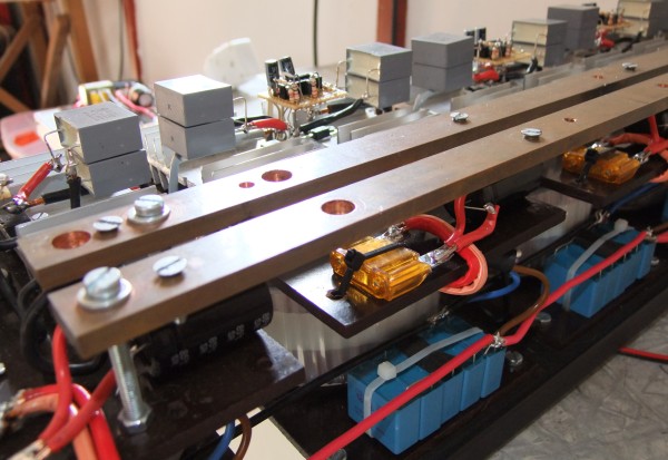
The inverter has been installed in an enclosure which has been designed to take 5X2000W units, i.e. 10 kW.