The Parallel Battery Charger is designed and developed for DIY purposes. It uses very simple techniques and is low cost. It can however only be used if batteries can be switched in parallel with the aid of isolator relays.
The Battery Charger consists of three main elements:
a. The Transformers, resistors and rectifiers
b. The Charger Controller with Indicators
c. The Battery Bank Relays
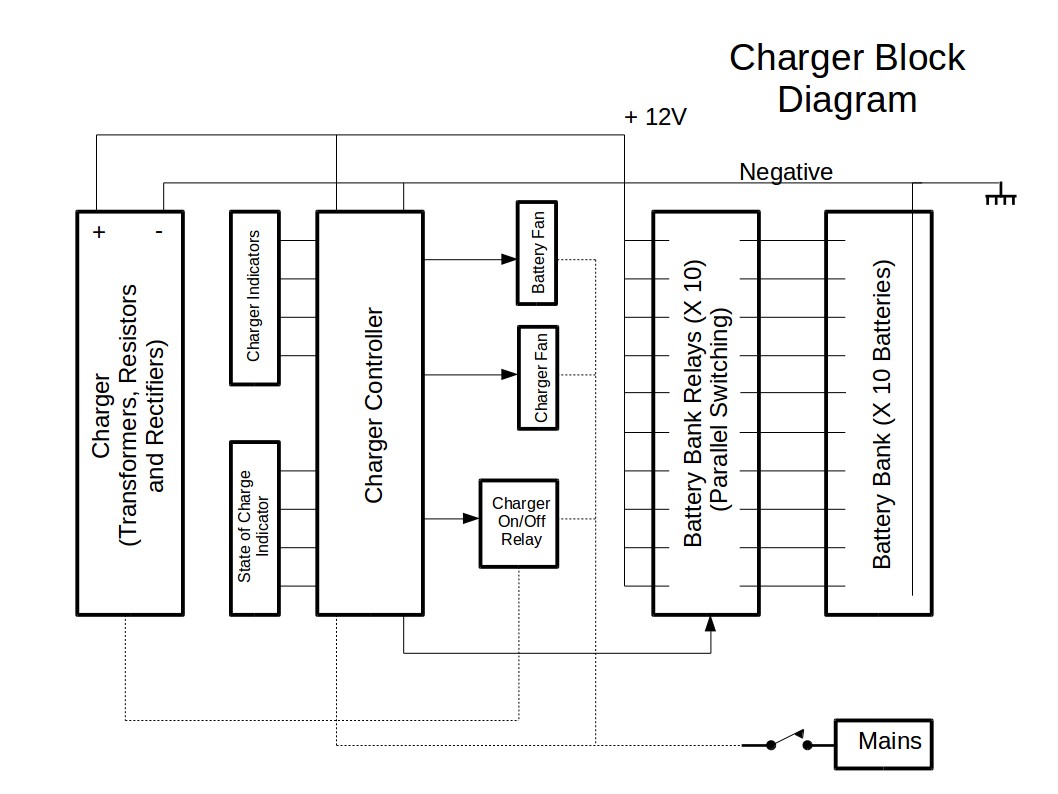
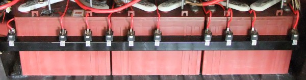
The Battery Bank Relays are used to switch the 10 Batteries in the Battery Bank in parallel. A 12V setup is obtained in this way. It is possible due to the fact that the EV Motor Controller switches all batteries off when in idle state, i.e. all batteries are then connected together with their negative poles and their positive poles are disconnected.
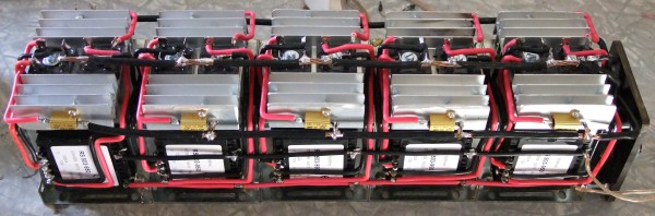
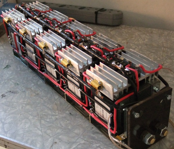
The Charger is built with 5 transformers of type RS 503-950, each equipped with a bridge rectifier and resistor. All components are available from http://za.rs-online.com/web/. The resistor is a 0.1 ohm resistor and is used to protect the transformer from over current conditions. The charger can deliver 80A into a 12V battery setup. The transformers are 12V dual secondary transformers (not center taped). They are connected in parallel and in-phase.
The Charger Controller performs the following functions:
- Switch the Battery Relays on/off and thereby connecting the EV Battery Bank Batteries in parallel.
- Measure the Battery Bank State of Charge and decide the period of charge.
- Switch the Battery Bank Fan and the Charger Fan on/off
- Control the Battery Charge Voltage on 14.3V by switching the Charger Relay on and off.
- Indicates the State of Charge using four LEDs
- Indicates the Charge Process Stage with four LEDs.

The Charge Controller is based on the ATmega8 processor.
The program is written in Basic Language. The listing is given below.
The program was created and compiled with BASCOM AVR and the programmer used is the USB-ISP programmer, both available from www.mcselec.com
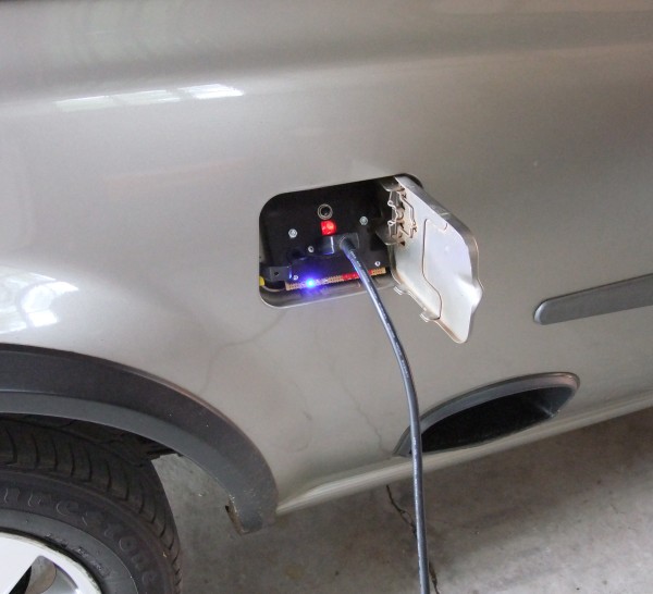
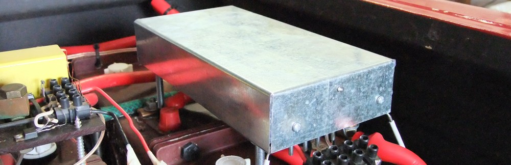
The Charger is installed in the back of the vehicle near the original petrol inlet flap.
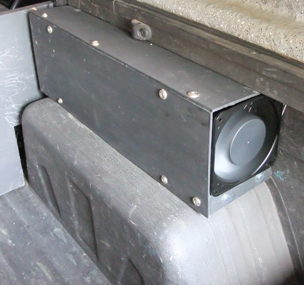
The Mains input is provided via an indicator pad installed behind the original petrol flap door. Mains input is taken from a standard household 15A 220V AC wall socket and is plugged into the charger by means of a standard kettle cord.