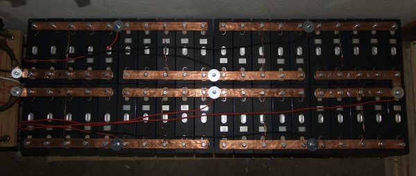
A Litium Ion Battery (of type LiFePO4) (LFP) is used for this solar system. The battery consists of 40 LFP cells of 120Ah, connected together to provide 24V for the inverters.
The LFP Cells are available from this company in the RSA – https://lithiumbatteriessa.co.za/collections/cells/products/3-2v-120ah-lithium-ion-phosphate-battery-cell.
The 40 cells have been connected as shown in the picture below:
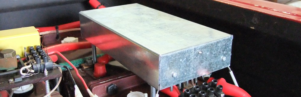
LFP cells need to be protected against over voltage during charging (above 3.6V) and low voltage during discharge (below 2.5V). The system uses the low voltage cut-out capability of the Inverters to protect the cells from a “too low voltage” (empty) condition. The Block Diagram for the cell over-charge (“too full”) protection electronics is shown below:
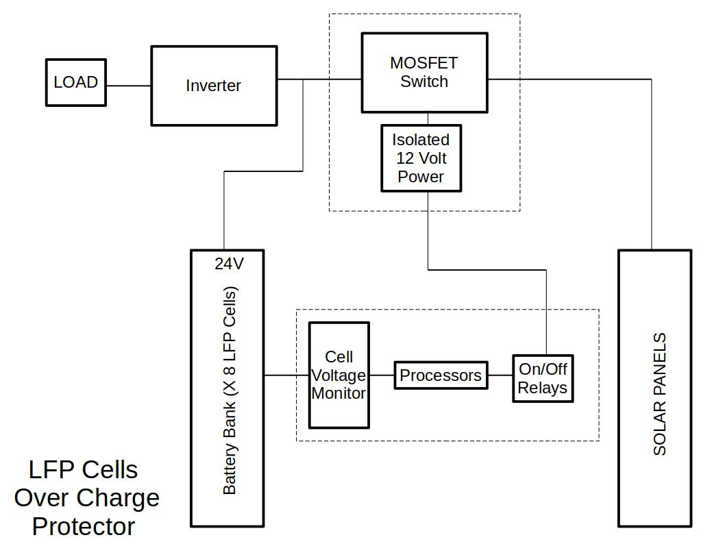
The Processors monitor the LFP Battery cell voltages and switch the Solar Panels off when any cell voltage exceeds 3.5V. The panels are disconnected from the battery by means of a Mosfet switch. The Solar Panels are switched back in after a short time-out period, and the process is repeated.
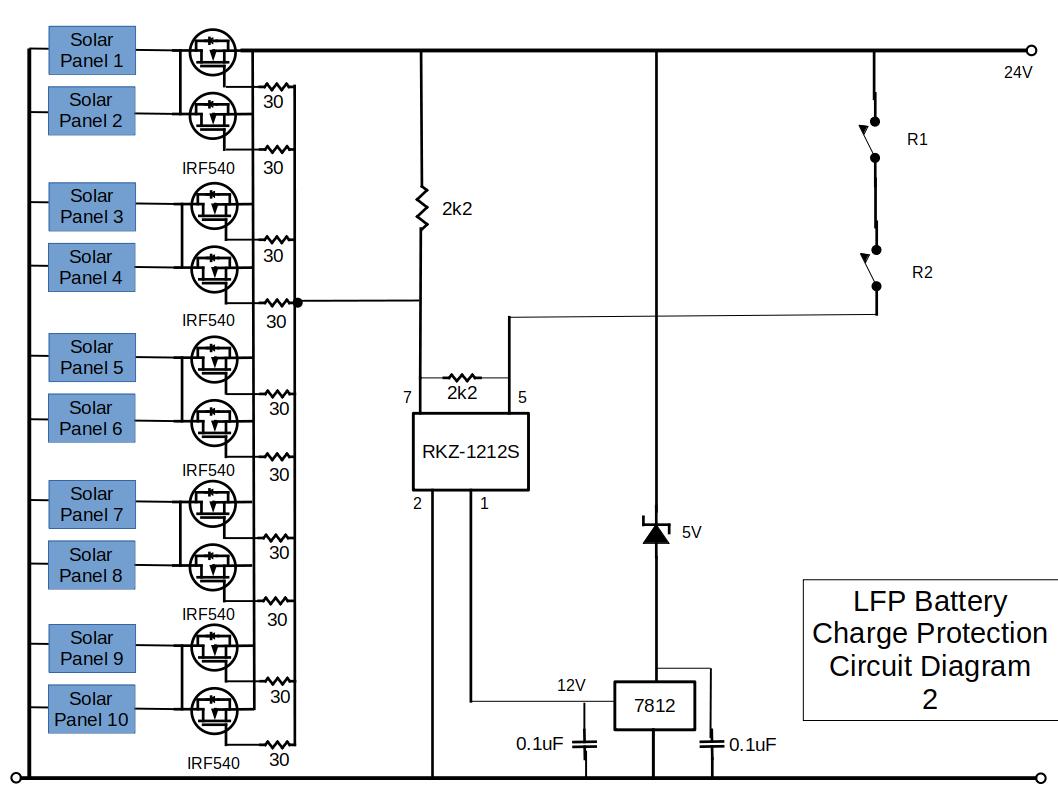
The circuit diagrams for the LFP Cell Protection electronics are shown below:
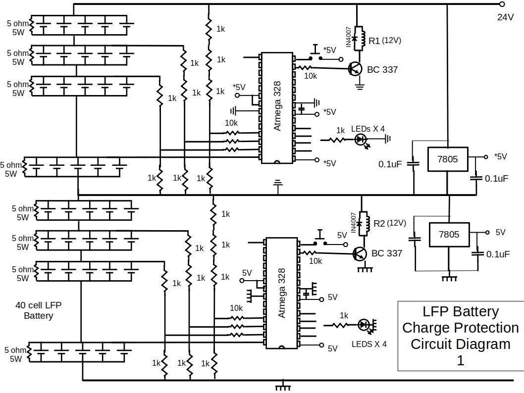
The battery is connected in a way that it has 8 “big-cells” in series to provide 24V. Each “big-cell” consists of 5 LFP cells in parallel.
Each of the 8 “big-cells” are provided with a 5W 5 Ohm balancing resistor. These resistors ensure that the “big-cell” voltages become equal over time.
The Micro Controllers monitor the 8 “big cell” voltages via a set of 0.1% accurate resistors. It decides when to switch the solar panels in or out, depending on the LFP ‘big cell” voltages. The Micro Controllers also display which cell reached the high voltage threshold of about 3.5V, by means of 8 LEDs.
The software program was created and compiled with BASCOM AVR and the programmer used is the USB-ISP programmer, both available from www.mcselec.com.
The program listing is given here: